The 7805 is the component most beginners meet the moment they try to run a 5V circuit off anything other than USB or a wall adapter — a 9V battery, a car’s 12V supply, a wall-wart that puts out slightly more than it claims. It’s a three-pin chip that takes a messy, higher, or unregulated input voltage and turns it into a clean, steady 5V, and it’s been in continuous production since the early 1970s for the same reason the 555 timer has: it’s cheap, it’s simple, and it just works.
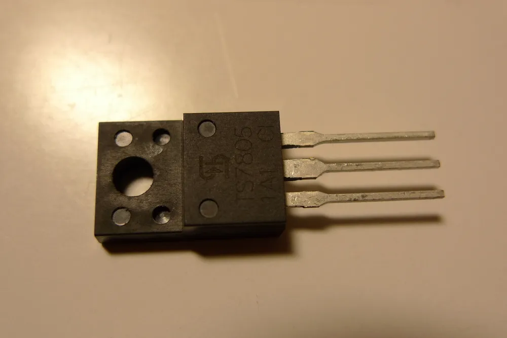
A 7805 linear voltage regulator, TO-220 package. Photo: Anonimski, CC0 (resized)
Pinout
Hover or tap a pin above to see what it does.
Looking at the chip with the printed label facing you and the pins pointing down, in the standard TO-220 package:
| Pin | Name | What it does |
|---|---|---|
| 1 | IN | Unregulated input voltage — needs to be at least a couple of volts above the 5V output for the regulator to work properly. |
| 2 | GND | Ground/common — also internally connected to the metal tab on the back of the package. |
| 3 | OUT | Regulated 5V output. |
That metal tab being tied to GND matters if you’re mounting the regulator to a shared metal heatsink alongside other components — since the tab is at ground potential, bolting it straight to a heatsink is normally fine, but it’s worth checking nothing else touching that heatsink is at a different potential.
How it actually works
Inside, the 7805 is built around a reference voltage source and a feedback loop that continuously adjusts an internal pass transistor to hold the output at exactly 5V, regardless of small changes in input voltage or how much current the circuit downstream is drawing. It’s a linear regulator, meaning it does this by burning off the excess voltage as heat rather than converting it efficiently the way a switching regulator would — which is the source of both its simplicity and its main limitation.
Input needs headroom above 5V. The regulator needs the input to sit at least about 2V above the 5V output — called the dropout voltage — to keep regulating properly. In practice that means a comfortable working input range of roughly 7V to 20V; below about 7V the output starts sagging below 5V, and above 20V or so you’re wasting an increasing amount of power as heat for no benefit.
Power dissipation is the real design constraint, not current. The 7805 is rated for up to 1A, but that number only tells half the story — the heat it has to shed is (Vin − 5V) × current drawn. Running it from a 9V battery at 200mA dissipates less than a watt, easily handled by the bare chip. Running it from 12V at a full amp means dissipating 7W, which will overheat and thermally shut down a bare TO-220 package in seconds — that situation needs a heatsink, and even then, 1A continuous is pushing it. If a project needs to drop a large voltage at real current, a switching buck converter is the better tool; the 7805 is really at its best when the input-to-output gap is small and the current draw is modest.
Capacitors: not strictly optional
Most 7805 circuit diagrams show two small capacitors, and skipping them is a common reason a “correctly wired” regulator circuit oscillates, is noisy, or is unstable under load:
- 0.33µF ceramic on IN, close to the pin — needed if the regulator is more than a few centimetres of wire away from the main filter capacitor on your power supply, to stop the regulator seeing high-frequency noise on a long input lead.
- 0.1µF ceramic on OUT, close to the pin — improves transient response and stability, particularly important if the load’s current draw changes quickly (switching digital logic, motors starting and stopping).
Both go between their respective pin and ground, placed physically close to the regulator’s legs rather than further down the board.
Common mistakes
Swapping IN and OUT. Feeding your input voltage into the OUT pin by mistake typically won’t destroy the chip outright, but it also won’t regulate anything — always double-check orientation against the printed label before powering up, especially on stripboard where a pin can easily land one hole off from where you meant it to.
No heatsink at real current draw. A 7805 that gets too hot to touch is telling you it’s dissipating more power than the bare package can shed — that’s a heatsink problem, not a faulty chip, and it will thermally shut down (or eventually fail) if left unaddressed rather than magically running cooler on its own.
Expecting more than 1A. Pushing near or past the 1A rating, especially with a large input-output voltage gap, is asking for thermal shutdown under load. If a project genuinely needs more current at 5V, look at a higher-current linear regulator or a switching buck converter instead of relying on a bare 7805.
Variants worth knowing
The 7805 is one member of the wider 78xx family — same TO-220 pinout, same basic design, just different fixed output voltages: the 7806 (6V), 7809 (9V), and 7812 (12V) are the other common ones, useful when a project needs a different fixed rail than 5V. There’s also a smaller surface-mount SOT-223 package version for compact boards, with the same three electrical functions in a different physical footprint — check the specific pin diagram on the datasheet before assuming it matches the TO-220 layout pin-for-pin.

