
The SG90 is the default small servo in nearly every beginner kit — cheap, light, and simple enough to have exactly three wires. That simplicity is also why it’s a common source of confusion: three wires means there’s nowhere to hide a wiring mistake, but it also means the servo has no protection built in against the one mistake beginners make most often, which is powering it from the wrong place.
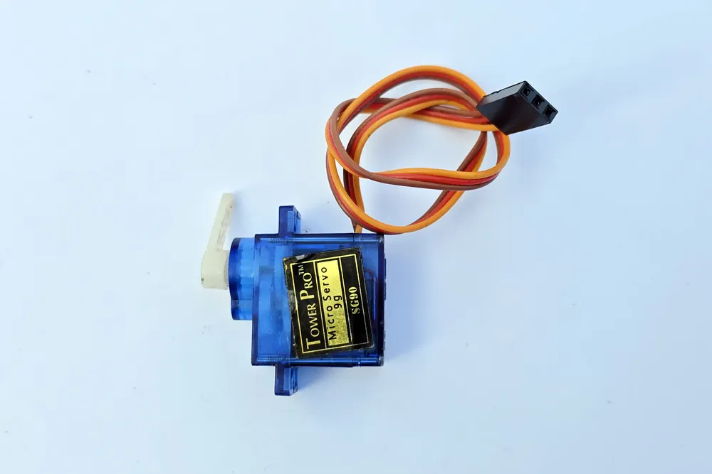
A TowerPro SG90 micro servo. Photo: Suyash Dwivedi, CC BY-SA 4.0 (resized)
Pinout
Three wires, colour-coded consistently across nearly every SG90 and SG90-clone on the market:
| Wire colour | Name | What it does |
|---|---|---|
| Orange (sometimes yellow) | Signal | PWM control signal from the microcontroller |
| Red | VCC | Power, 4.8–6V |
| Brown (sometimes black) | GND | Ground |
If a specific board’s colours don’t match this — some clones swap red/brown positions relative to the connector shell — the physical connector itself is the reliable guide: it’s keyed so it only plugs into a standard three-pin servo header one way round, and the signal wire is always the one nearest the notch/tab side of the connector on genuine and clone SG90s alike.
How the control signal works
The SG90 reads position from a PWM signal, but not from the duty cycle the way an LED dimmer would — it reads the pulse width, on a 50Hz (20ms period) signal. Roughly:
- 1ms pulse ≈ 0° (fully one direction)
- 1.5ms pulse ≈ 90° (centre)
- 2ms pulse ≈ 180° (fully the other direction)
Exact endpoints vary a little between individual servos and clones, which is why most libraries (Arduino’s Servo.h, for instance) expose an attach() call that lets the pulse-width range be tuned if a servo doesn’t quite reach its expected physical limits with the library’s defaults.
Wiring
- Signal (orange) to any digital pin — on Arduino,
Servo.hhandles the PWM generation in software so it doesn’t need to be a hardware-PWM pin specifically. - VCC (red) to a 5V supply — not directly from a microcontroller board’s onboard 5V regulator if more than one servo is involved, or if anything else is sharing that rail. See below.
- GND (brown) to ground, shared with the microcontroller’s ground even if the servo is powered from a separate supply.
Why powering it from the microcontroller’s 5V pin causes problems
A single SG90 briefly draws a noticeable current spike every time it moves, and stalls (pushed against a mechanical limit, or under load) can draw considerably more. An Arduino or similar board’s onboard 5V regulator is sized for the board itself plus light loads — it is not sized to also supply a servo’s movement spikes, and asking it to do so is the single most common cause of two closely related symptoms: the servo jittering instead of moving smoothly, and the whole board resetting when the servo moves, because the voltage sag from the servo’s current draw dips below what the microcontroller’s own brownout detector will tolerate.
The fix is a dedicated 5V supply for the servo (a separate regulated supply, or 4×AA batteries for a rough-and-ready bench setup), with its ground tied to the microcontroller’s ground — common ground is required for the signal wire to mean anything, even though the power itself comes from two separate places. This gets more important, not less, with each additional servo added to a project — two or three servos moving at once on a board’s onboard regulator is a very reliable way to produce exactly this failure.
Common mistakes
Powering multiple servos from the microcontroller’s 5V pin. Covered above — the most frequent cause of both jitter and unexplained resets.
Wiring signal and power backwards. The connector is keyed to prevent this on a standard three-pin header, but breadboard wiring done by hand from loose wires has no such protection — double-check against the colour table above before powering on.
Expecting continuous rotation. The SG90 is a positional servo with roughly 180° of mechanical travel, not a continuous-rotation motor — asking it to spin continuously (rather than a specific “continuous rotation” variant sold separately) will just drive it against its internal end-stop.
Forcing it past its mechanical limit by hand. Manually rotating an SG90’s horn past its end-stop while powered, or with real force while unpowered, can strip the small internal gears — they’re plastic on the standard SG90, and it’s a common failure mode for an otherwise perfectly good servo.
If you don’t have one on the bench already, a pack of metal-gear micro servos is a sturdier alternative to the standard plastic-gear SG90 if a project is going to be pushing against real resistance. If jitter or resets are the actual problem you’re chasing right now, why is my servo motor jittering goes through the full troubleshooting list.

