The 555 has been in continuous production since 1971, and it’s still the first IC most people wire up after LEDs and resistors. Part of that longevity is that it’s genuinely useful — LED flashers, tone generators, debounced switches, PWM motor control — and part of it is that the failure modes are so consistent you can diagnose them from across the room: chip gets warm and does nothing, or it oscillates but at completely the wrong speed. Both usually trace back to the same one or two pins.
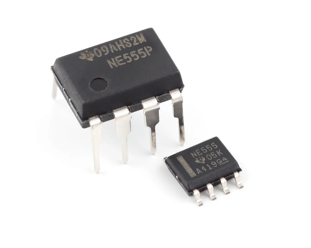
NE555 timer IC in DIP and SOIC packages. Photo: Swift.Hg, CC BY-SA 3.0 (resized)
Pinout
Hover or tap a pin above to see what it does.
| Pin | Name | What it does |
|---|---|---|
| 1 | GND | Ground — connect to the negative supply rail (0V). |
| 2 | TRIG (Trigger) | Pulled below 1/3 Vcc, this starts the timing cycle and forces the output high. |
| 3 | OUT (Output) | Switches between roughly 0V and Vcc; drives your LED, buzzer, or logic input. |
| 4 | RESET | Pull below about 0.7V to force the output low immediately, overriding everything else. Tie to Vcc if unused. |
| 5 | CTRL (Control Voltage) | Overrides the internal 2/3 Vcc reference. If unused, decouple to ground with a small (~10nF) capacitor. |
| 6 | THRES (Threshold) | When this rises above 2/3 Vcc, the timing interval ends and the output goes low. |
| 7 | DISCH (Discharge) | Open-collector pin that sinks current to ground during timing — usually used to discharge the timing capacitor. |
| 8 | VCC | Positive supply, 4.5–15V for the classic bipolar NE555 (lower for CMOS variants — see below). |
How it actually works inside
Strip away the datasheet block diagram and the 555 is three things wired together: two voltage comparators, an SR flip-flop, and a transistor that acts as a switch to ground.
The two comparators watch two different pins against two fixed reference points, both derived from Vcc through an internal resistor divider (this is where the “555” name comes from — three 5kΩ resistors in series):
- The threshold comparator watches pin 6. When that voltage climbs above 2/3 Vcc, it flips the internal flip-flop so the output goes low.
- The trigger comparator watches pin 2. When that voltage drops below 1/3 Vcc, it flips the flip-flop the other way, so the output goes high.
Whichever one fired most recently wins — that’s the flip-flop’s job, holding the output state until the other comparator overrides it. Pin 7 (discharge) is just a transistor to ground that switches on whenever the output is low, which is what lets the chip discharge a timing capacitor on its own without any external switching.
Once you see it as “two comparators fighting over a flip-flop,” the three operating modes stop being separate things to memorise and become the same circuit used three different ways:
- Monostable — one resistor and capacitor on threshold/discharge, triggered by a pulse on pin 2. Output goes high for a fixed time, then low, then sits there until triggered again. This is the “delay” or “one-shot” mode — a doorbell that stays lit for exactly 3 seconds, say.
- Astable — the output is fed back to trigger itself, so it free-runs continuously between high and low. This is the LED flasher / tone generator mode, and the one most people build first.
- Bistable — reset and trigger used as separate set/reset inputs, capacitor removed entirely. The chip just becomes a basic flip-flop — rare in practice, but it’s a useful reminder that the flip-flop is the chip, and the timing components are just how you drive it.
Wiring mistakes that actually cause problems
- Reset pin left floating. Pin 4 is active-low and internally it’s not reliably pulled high on all variants. A floating reset pin picks up noise, and the chip resets itself at random — which looks exactly like “intermittent, no clear cause” until you tie it straight to Vcc.
- Skipping the control voltage decoupling capacitor. Pin 5 sits directly on the internal reference divider. Leave it unconnected on a breadboard next to noisy wiring (like a nearby motor or relay) and that noise couples onto the 2/3 Vcc threshold itself, shifting your timing unpredictably. A 10nF capacitor from pin 5 to ground is cheap insurance even when you don’t need to use the pin.
- Driving something straight off the output pin that draws too much current. The 555 can source or sink around 200mA on paper, but a motor, solenoid, or anything inductive needs a transistor or MOSFET switching it, with a flyback diode across the load — never the chip’s output pin directly. Skip this and you’ll eventually kill the chip via voltage spikes when the load switches off.
- Wrong timing resistor values. Astable frequency and duty cycle come from the two timing resistors and the capacitor (roughly f = 1.44 / ((R1 + 2×R2) × C) for the classic configuration). Getting a period wildly different from what you calculated almost always means a resistor value misread rather than a chip fault — check those before suspecting the IC.
Which 555 variant is in your hand
“555” isn’t one chip, it’s a whole family, and the differences aren’t just academic:
- NE555 / bipolar original. The classic. Needs at least 4.5V to run reliably, and its output doesn’t swing all the way to the rails (expect it to sit a volt or so short of Vcc/GND at each extreme).
- LM555. Functionally the same bipolar design as the NE555 from a different manufacturer — pin-compatible, same voltage range, same output-swing behaviour.
- CMOS variants (TLC555, LMC555, ICM7555). Run down to 2V, draw a fraction of the quiescent current, and swing output much closer to the full rail-to-rail range. They’re also more sensitive to static and to the control-voltage-pin noise issue above, since CMOS inputs present much higher impedance.
If a circuit that works fine on the bench misbehaves the moment you swap in whatever 555 was in the parts drawer, checking which variant is actually in the socket is worth doing before anything else.
If you don’t already have one on the bench, a multipack of plain bipolar NE555 timer ICs is a cheap way to have a few spares around — worth having more than one, since it’s easy to let the magic smoke out of the first one while you’re still learning its limits.
If you haven’t wired up a breadboard circuit before, how a breadboard is actually connected underneath is worth reading first — most “the 555 isn’t working” reports turn out to be a breadboard wiring issue once you trace them back.

