A breadboard looks like a simple grid of holes, and that’s exactly what trips people up. The holes aren’t all independent, and they’re not all connected to their neighbours either — the pattern underneath is specific, and not knowing it is behind a huge share of “why isn’t this working” moments.
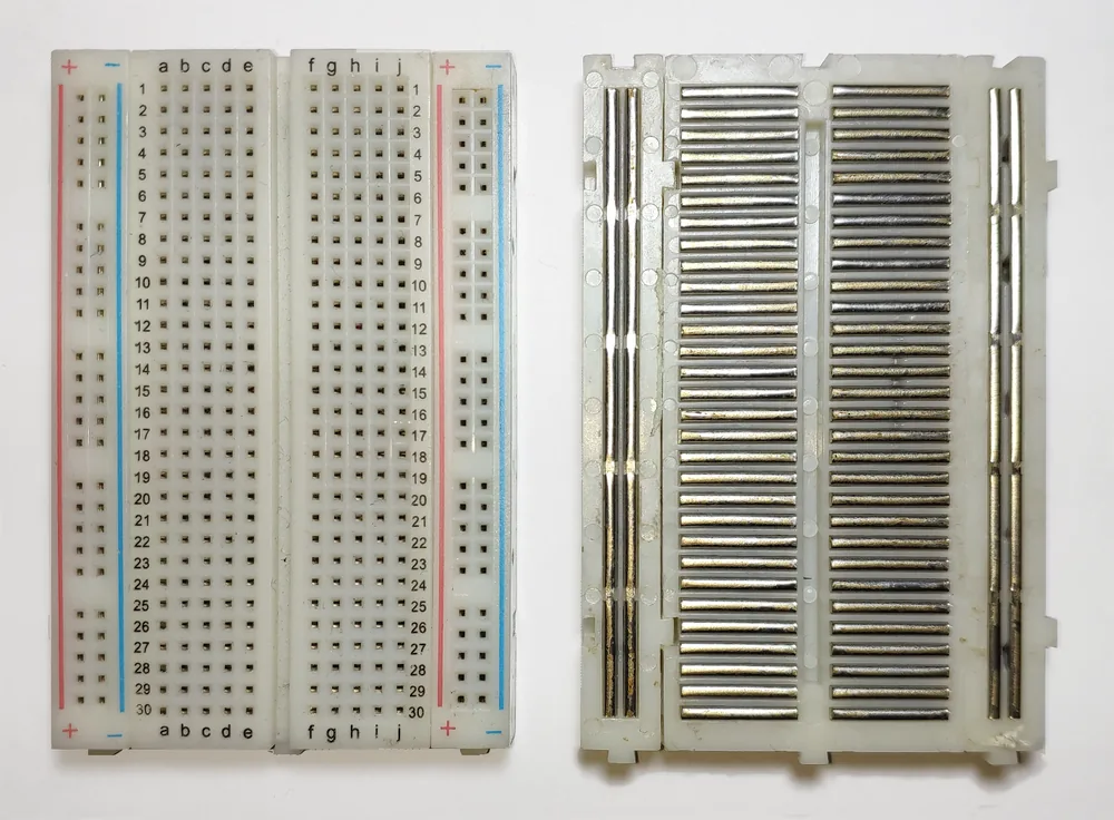
A solderless breadboard, top and bottom view. Photo: Guhuru, CC0 (resized)
What’s actually connected underneath
Ignore the holes and think in two zones: the terminal strips in the middle, and the power rails along the top and bottom.
Terminal strips
The middle of the board is split into two halves by a gap running down the centre (sized to straddle a DIP chip). Within each half, holes are wired in short columns of five, running top to bottom:
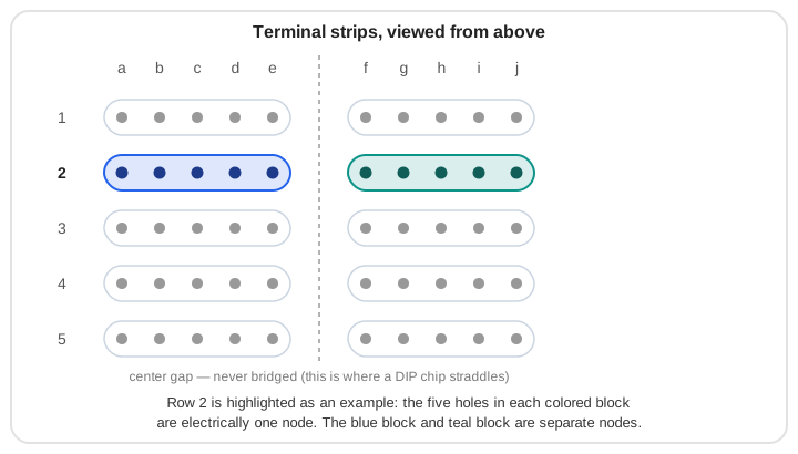
Each column — a through e in row 1, say — is one electrical node. Plug a resistor leg into 1a and a wire into 1c, and they’re connected. Move to row 2 and you’re on a completely different node. The columns on the other side of the centre gap (f through j) are separate again — the gap is not bridged, which is exactly why it’s the standard spot to seat a chip: each row of pins lands on its own independent group of five holes.
Power rails
The rows running along the top and bottom edges work differently — they run the long way, usually marked with a red line (+) and a blue or black line (−):
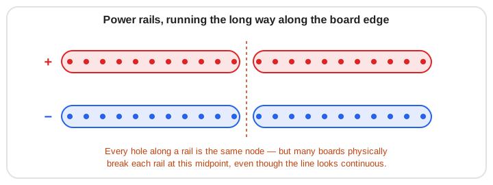
Every hole along a rail is connected to every other hole on that same rail — that’s what makes them useful for distributing power and ground to multiple components at once.
Where this trips people up
- Assuming the centre gap is bridged. It isn’t. A wire from row 3 on the left half won’t connect to row 3 on the right half unless you physically link them with a jumper.
- Assuming the power rails run the full length of the board uninterrupted. On full-size and half-size breadboards, the rails are often physically split at the midpoint, even though the red/blue line looks continuous. If components on one end of the board aren’t getting power, check for this break before anything else — it’s the single most common cause of “half my circuit works and half doesn’t.”
- Shorting a row by accident. Two component legs in the same five-hole column are connected, full stop — useful when you mean it, a dead short when you don’t. This is an easy way to fry an LED or a sensor without realising why.
- Forgetting which side of the gap a chip’s pins are on. Straddle the centre gap with a chip, and each pin gets its own isolated row to build a circuit around — but it’s easy to lose track of which physical row corresponds to which pin once a few jumpers are in place.
Putting it together
A typical layout: bring +5V and ground from your power source into the top rails, then run short jumpers from the rails down into the terminal strip rows where you need them. Components that need to be in series go in different rows; components that need to share a connection (like two resistors both going to ground) go in the same row, or both connect to the rail directly.
Before you power anything on, trace back through: is each component actually sitting in the row you think it is, and does that row actually connect where you expect? A multimeter’s continuity mode is the fastest way to confirm a connection you’re not sure about, rather than guessing and powering on.
Once this clicks, the next step is putting it into practice: wiring up your first Arduino project and blinking an LED. If it doesn’t light up, why an LED won’t light walks through the most common causes, breadboard-wiring mistakes included.

