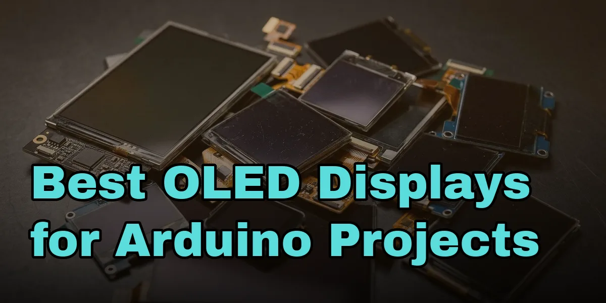
Once you’ve got past blinking an LED, adding a small screen is usually the next thing that makes a project feel real — a sensor reading, a menu, a status message, something more satisfying than watching numbers scroll past in the Serial Monitor. OLED displays are the obvious choice over an LCD for this: no backlight to wire up, genuinely black backgrounds since unlit pixels draw no power at all, and sharp, high-contrast text even on a tiny screen.
Before picking one, it’s worth understanding the two or three specs that actually determine whether it’ll be a five-minute job or an evening of debugging.
What actually matters when choosing
Interface: I2C over SPI, almost every time. OLED modules come wired for either I2C (just four wires: VCC, GND, SDA, SCL) or SPI (six or seven wires, faster refresh but more pins used and more complex wiring). Unless you’re driving a large display fast enough that I2C’s refresh rate becomes a real bottleneck, I2C is the easier starting point — fewer wires, and you can share the same two data pins with other I2C sensors on the same bus.
Driver chip: check it’s SSD1306 (or know you’re not). This is the single most common source of “I wired it exactly right and it’s still blank” reports. The Arduino library you use has to match the chip actually driving the panel — the ubiquitous SSD1306 is supported directly by Adafruit’s well-maintained Adafruit_SSD1306 library, while some cheaper or oddly-sized panels use an SH1106 controller instead, which needs a different library (Adafruit_SH110X or similar) despite looking visually identical and often being sold under near-identical listings. Check the listing or the module’s silkscreen before assuming.
Size and resolution. For general hobbyist use, 0.96" at 128×64 pixels is the sweet spot — big enough to show a few lines of readable text or a simple graph, small enough to fit into almost any enclosure. A 128×32 panel of the same physical width trades vertical space for a slimmer profile, good for a single status line rather than a menu. Larger 1.3" and up panels exist and are easier to read from a distance, but cost more and are harder to squeeze into a compact build.
I2C address. Most SSD1306 modules default to 0x3C, but a few ship set to 0x3D. If a scan with an I2C scanner sketch doesn’t turn up 0x3C, try 0x3D before assuming the module is faulty — this single-digit mismatch is a very common cause of “nothing shows up” on an otherwise correctly wired display.
The safe default pick
For a first OLED, a 0.96" I2C OLED module ticks every box above — SSD1306 driver, I2C interface, 128×64 resolution, and it comes as a three-pack, which matters more than it sounds like it should. OLED panels are genuinely easy to kill with a static discharge or a wiring mistake while you’re still learning, and having two spares on hand means a dead module doesn’t stall a project for a week while a replacement ships.
Wiring it up
I2C keeps this simple regardless of which specific module you land on:
| OLED pin | Connects to |
|---|---|
| VCC | 5V or 3.3V (check the module — most are 3.3–5V tolerant, but some 3.3V-only boards exist) |
| GND | GND |
| SCL | A5 on an Uno/Nano, or the ESP32/ESP8266’s designated SCL pin |
| SDA | A4 on an Uno/Nano, or the designated SDA pin |
If you haven’t wired anything on a breadboard before, how a breadboard is actually connected underneath is worth reading first — a surprising number of “the display won’t turn on” cases turn out to be a breadboard row issue rather than anything to do with the OLED itself.
