Every beginner circuit with an LED in it needs a resistor in series to keep the current down to something the LED can survive. Getting the value right isn’t guesswork — it’s one calculation, and once it clicks you’ll never need to look it up again.
The formula
R = (Vsupply − Vf) / I
- Vsupply — the voltage you’re powering the LED from (5V from an Arduino pin, 3.3V from an ESP32 pin, a 9V battery, whatever it is)
- Vf — the LED’s forward voltage, the voltage it “uses up” once it’s conducting
- I — the current you want flowing through it, in amps (so 0.02 for 20mA, not 20)
The result is the resistor value in ohms.
Forward voltage by colour
This is the part that trips people up, because it’s not one number — it depends on the LED’s colour, since that’s tied directly to the semiconductor material inside it:
| Colour | Typical Vf |
|---|---|
| Red, yellow, orange | 1.8–2.2V |
| Green | 2.0–3.2V |
| Blue, white, UV | 2.9–3.4V |
If you don’t know the exact figure for the LED in your hand, use the middle of the range for its colour — the calculation isn’t sensitive enough for it to matter much either way.
A worked example
Say you’re driving a standard red LED from an Arduino’s 5V, and you want a safe, comfortably bright 15mA:
R = (5V − 2.0V) / 0.015A
R = 3V / 0.015A
R = 200Ω
200Ω isn’t a standard resistor value, so round up to the nearest one you’ve got — 220Ω is the usual choice here, and it’s a value worth keeping a handful of on hand for exactly this reason. Rounding up means slightly less current than the target, which is the safe direction to round; rounding down pushes the LED slightly past what you calculated for.
Once you know the value you need, finding the right physical resistor in a mixed parts bin means reading its colour bands rather than measuring every candidate with a multimeter:
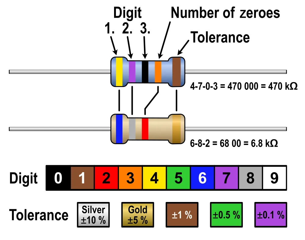
The resistor colour code chart. Image: Knarfili, CC0
Why blue and white LEDs are the awkward case
Run the same calculation for a white LED (Vf ≈ 3.2V) off a 3.3V ESP32 pin at 15mA:
R = (3.3V − 3.2V) / 0.015A
R = 0.1V / 0.015A
R ≈ 7Ω
There’s almost no headroom left, and a 7Ω resistor barely limits anything — a small amount of supply voltage variation could push current uncomfortably high. This is exactly why blue and white LEDs are harder to drive cleanly from low-voltage logic pins than red or yellow ones: there just isn’t much voltage left over once the LED’s own forward drop is accounted for. If you’re stuck with a setup like this, dropping the target current a bit (to 10mA, say) gives the resistor a bit more to actually do, or powering the LED from a higher rail (5V instead of 3.3V) restores proper headroom.
What current to actually aim for
15–20mA is the standard target for a normal 5mm LED and is bright without stressing it. Small SMD or “indicator” LEDs are often happiest lower, around 2–5mA — check the datasheet or the seller’s listing if you have one, since running a small indicator LED at 20mA can shorten its life or blow it outright. When in doubt, starting at the lower end and going brighter if needed is the safer direction.
One resistor per LED, not one resistor for several
If you’re wiring multiple LEDs in parallel off the same supply, each one needs its own series resistor, not one shared resistor for the group. LEDs don’t have identical forward voltages even within the same batch, so the one with the slightly lower Vf will hog more of the shared current and run hotter than the others — sharing a resistor risks losing one LED to it while the rest stay dim. It’s a little more wiring, but it’s the only way to guarantee each LED gets a predictable, safe current.
If you’ve done the maths and the LED still won’t light, the resistor value usually isn’t the cause — why an LED won’t light covers the other, more common culprits, starting with polarity.

