The LM358 is the op-amp most people meet first without realising it’s an op-amp — it’s buried inside cheap sensor breakout boards, comparator modules, and “smart” relay boards doing threshold detection, because it’s cheap, it’s a genuine two-for-one (two independent amplifiers in one DIP-8 package), and unlike a lot of older op-amps it’s happy running from a single supply rail instead of needing a split positive/negative supply.
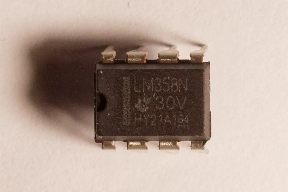
An LM358 dual operational amplifier IC, DIP-8 package. Photo: Retired electrician, CC0 (resized)
Pinout
Hover or tap a pin above to see what it does.
Looking at the chip from above, notch or dot at pin 1, in the standard DIP-8 package:
| Pin | Name | What it does |
|---|---|---|
| 1 | OUT1 | Output of op-amp A |
| 2 | −IN1 | Inverting input of op-amp A |
| 3 | +IN1 | Non-inverting input of op-amp A |
| 4 | GND / V− | Negative supply — ground on a single-supply circuit, or the negative rail on a split supply |
| 5 | +IN2 | Non-inverting input of op-amp B |
| 6 | −IN2 | Inverting input of op-amp B |
| 7 | OUT2 | Output of op-amp B |
| 8 | VCC / V+ | Positive supply, 3–32V single-supply (or ±1.5V to ±16V split supply) |
The two amplifiers, labelled A and B here, are completely independent internally — they only share the two power pins. Nothing stops you from using one for a sensor comparator and the other for a totally unrelated amplification job on the same board.
The thing that actually matters: it’s a single-supply op-amp
Classic op-amps expect a split supply — a positive rail, a negative rail, and ground in between — so the input and output can swing above and below 0V. The LM358 was specifically designed to work from a single positive supply with no negative rail at all, which is why it turns up in so many battery-powered and microcontroller-adjacent projects: there’s no need to generate a negative voltage just to run an amplifier.
That convenience comes with a real limitation, and it’s the single most common “why doesn’t my LM358 circuit work” cause: the output can’t swing all the way down to 0V or all the way up to V+. With a 5V supply, expect the output to bottom out somewhere around 0V (the LM358’s output stage is unusually good at pulling close to ground compared to most op-amps) but top out roughly 1.5V short of the supply rail — so on a 5V supply, don’t expect a clean swing past roughly 3.5V. Circuits copied from a general “op-amp circuit” reference that assume the output can reach the full supply rail will read wrong, or clip, near the top of that range.
The inputs have a similar restriction: the input common-mode range includes ground but doesn’t quite reach V+, so an input signal that swings right up to the supply rail can behave oddly near the top of its range too.
Comparator vs amplifier use
The LM358 shows up in two very different roles, and it’s worth being clear on which one a given circuit is doing:
As a linear amplifier, it’s wired with negative feedback — a resistor (or resistor network) from the output back to the inverting input — so the output tracks a scaled, amplified version of the input signal smoothly.
As a comparator, there’s no feedback at all — the two inputs are compared directly, and the output slams to one rail or the other depending on which input is higher. This is the role it plays in most of the cheap sensor modules it’s found inside: a photoresistor or thermistor forms a voltage divider against a reference, that divider feeds one input, a potentiometer sets a threshold on the other input, and the LM358’s output flips a digital HIGH or LOW as the sensor crosses that threshold — which is why so many of those modules have a little screw-adjustable trimmer sitting right next to the chip.
The LM358 isn’t marketed as a dedicated comparator chip the way something like the LM393 is, and its output stage is genuinely slower to switch than a purpose-built comparator — fine for a slowly-changing sensor threshold, not fine for anything switching fast.
Common mistakes
Expecting the output to reach 0V or V+ cleanly. Covered above, but it’s worth repeating: a “why is my output stuck at 3.6V on a 5V supply” report is almost always this limitation, not a fault.
Leaving an unused half of the chip floating. If only one of the two amplifiers is used in a design, the other one’s inputs shouldn’t be left unconnected — a floating input can pick up noise, swing the unused amplifier’s output unpredictably, and in some layouts increase power draw or crosstalk into the amplifier actually being used. Tie unused inputs to a defined voltage, typically ground or the midpoint of the supply.
Mixing up which input is inverting. Pins 2 and 3 (or 6 and 5) look symmetric on the pinout table but do opposite things — feeding a signal into the wrong one of the pair inverts the output relative to what the circuit was designed to do, which is an easy trace-back mistake on stripboard where the two input legs are one hole apart.
Assuming fast response. The LM358’s slew rate is modest (around 0.3V/µs) and its gain-bandwidth product tops out around 1MHz. It’s plenty for audio-range signals and slow sensor thresholds, but it’s the wrong choice for anything switching in the microsecond range — that’s a job for a dedicated comparator or a faster op-amp.
Variants worth knowing
The LM358 is one half of a closely related family: the LM324 is essentially the same design with four amplifiers instead of two, in a 14-pin package, useful when a project needs more channels than one LM358 provides. The LM393 is a dual comparator built on similar principles but optimised specifically for fast switching rather than linear amplification — worth reaching for instead of the LM358 if a circuit genuinely needs comparator speed. Pin-for-pin, none of these are drop-in replacements for each other; check the datasheet pinout before assuming compatibility.
If you don’t have one on the bench already, a pack of LM358P DIP-8 op-amp ICs is cheap enough to keep spares around. If you haven’t wired up a breadboard circuit before, how a breadboard is actually connected underneath is worth reading first — most “the circuit does nothing” reports trace back to a breadboard wiring issue rather than the chip itself.

