The LM386 is the chip behind most “mini amplifier” hobby projects — battery-powered speaker boxes, guitar practice amps, adding sound to an Arduino project that only outputs a weak line-level signal. It’s been around since the late 1970s and it’s stuck around for the same reason the 555 timer has: it needs almost nothing around it to work, it runs happily from a single low-voltage supply (no split rails, no separate op-amp power section), and a 9V battery is enough to drive a small speaker to a genuinely useful volume.
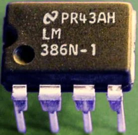
An LM386N-1 audio amplifier IC, DIP-8 package. Photo: Samba pa ti, public domain (resized)
Pinout
Hover or tap a pin above to see what it does.
Looking at the chip from above, notch or dot at pin 1, in the standard DIP-8 package:
| Pin | Name | What it does |
|---|---|---|
| 1 | GAIN | Gain set 1 — paired with pin 8. Leave open for the default gain of 20. |
| 2 | −IN | Inverting input — normally tied to ground via the input network. |
| 3 | +IN | Non-inverting input — your audio signal goes in here, through a coupling capacitor. |
| 4 | GND | Ground/common. |
| 5 | VOUT | Amplified output, fed to the speaker through a coupling capacitor. |
| 6 | VS | Supply voltage, 4–12V (up to 18V on the LM386N-4). |
| 7 | BYPASS | Taps the internal reference — leave unconnected, or decouple with a capacitor to cut hum on a noisy supply. |
| 8 | GAIN | Gain set 2 — paired with pin 1. |
How it works
Inside, the LM386 is a small op-amp-based amplifier with a fixed internal feedback network, built specifically to drive a low-impedance load (an 8Ω speaker) directly from its output pin — most general-purpose op-amps can’t do that; their outputs are designed to drive high-impedance inputs on the next stage, not a speaker coil. That’s the whole point of the chip: it’s an op-amp plus an output stage beefy enough to skip a separate power-amp transistor stage entirely.
It runs from a single supply rail rather than the plus/minus split supply a lot of op-amp circuits need, which is a large part of why it’s the go-to chip for a simple battery-powered amp — there’s no need to generate a negative rail just to amplify audio.
Setting the gain
Out of the box, with pins 1 and 8 left unconnected, the LM386 has a fixed gain of 20 (26dB) — enough for a lot of line-level sources, but not much for a weak signal like a bare electret microphone or a crystal earpiece.
Bridging pins 1 and 8 with a capacitor (10µF is the classic value) removes an internal 1.35kΩ resistor from the feedback network entirely, raising the gain to 200 (46dB) — ten times louder for the same input level. For something in between, a resistor in series with that capacitor between pins 1 and 8 sets an intermediate gain; smaller resistor, closer to 200, larger resistor, closer to 20. This is the one control most LM386 breadboard circuits get wrong in one of two directions: either nothing happens because gain-200 was expected but pins 1/8 were left open, or the amp screams with distortion because a mic-level signal got the full gain-200 treatment when gain-20 would have been plenty.
A minimal working circuit
A basic LM386 amp needs surprisingly little around it:
- Input coupling capacitor (around 0.1–1µF) between the signal source and pin 3 (+IN), to block any DC offset on the source from reaching the input.
- Output coupling capacitor (a few hundred µF, electrolytic) between pin 5 (VOUT) and the speaker — the LM386’s output sits at roughly half the supply voltage at rest, and that DC needs blocking before it reaches the speaker coil.
- Supply decoupling capacitor (around 0.1µF ceramic, plus a larger 100µF+ electrolytic) between pin 6 (VS) and ground, placed close to the chip.
- Zobel network — a 10Ω resistor in series with a 0.05µF capacitor, from the output (after the coupling cap) to ground. Not strictly required for it to make sound, but it damps high-frequency oscillation that a bare speaker’s inductance can otherwise trigger, and its absence is a common cause of a faint whine or hiss riding on top of the audio.
Pin 7 (BYPASS) can usually be left unconnected on a clean, well-regulated supply; on a noisy one — a cheap switching wall-wart, or a supply shared with a motor — decoupling it to ground with a 10µF capacitor noticeably quiets hum.
Common mistakes
Expecting gain-200 volume with pins 1/8 left open. The default gain of 20 is quiet with a typical line-level source. Before assuming the chip or wiring is faulty, check whether the circuit actually needs the gain capacitor across pins 1 and 8.
No output coupling capacitor. Wiring the speaker directly to pin 5 puts the LM386’s resting DC offset straight across the voice coil, which wastes power, can audibly distort the sound, and over time can damage a small speaker. The output cap is not optional.
Skipping supply decoupling and getting motorboating. A “putt-putt” low-frequency oscillation, distinct from clean audio, is the classic symptom of an underdecoupled supply rail on a single-supply audio amp — add the capacitor close to pin 6 before suspecting anything else.
Driving the input straight from a high-impedance source with no coupling cap. A bare piezo element or an ungrounded signal source can carry enough DC bias to upset the input stage’s operating point; the input coupling capacitor is there for the same reason as the output one.
Variants worth knowing
“LM386” isn’t a single fixed part — the trailing suffix sets the maximum supply voltage: the plain LM386N-1 and LM386N-3 are rated to 12V, while the LM386N-4 is rated up to 18V. Pinout and gain-setting behaviour are identical across all three; only the safe supply range changes, so it’s worth checking which suffix is actually in hand before assuming a 9V battery project can be pushed to a higher-voltage supply for more volume.
If you don’t have one on the bench already, a pack of LM386N DIP-8 amplifier ICs is cheap enough to keep a few spares around. If you haven’t wired up a breadboard circuit before, how a breadboard is actually connected underneath is worth reading first — most “the amp does nothing” reports trace back to a breadboard wiring issue rather than the chip itself.

