The Pico is a different animal from the rest of the Raspberry Pi family — it’s not a Linux computer with a 40-pin header bolted on, it’s a bare RP2040 microcontroller board, closer in spirit to an Arduino than to a Raspberry Pi 4. But it happens to share the same 40-pin, 0.1" header pitch, which causes a specific kind of confusion: the physical layout looks familiar, but almost none of the pin functions match a full-size Pi’s GPIO header. Treat it as its own thing.
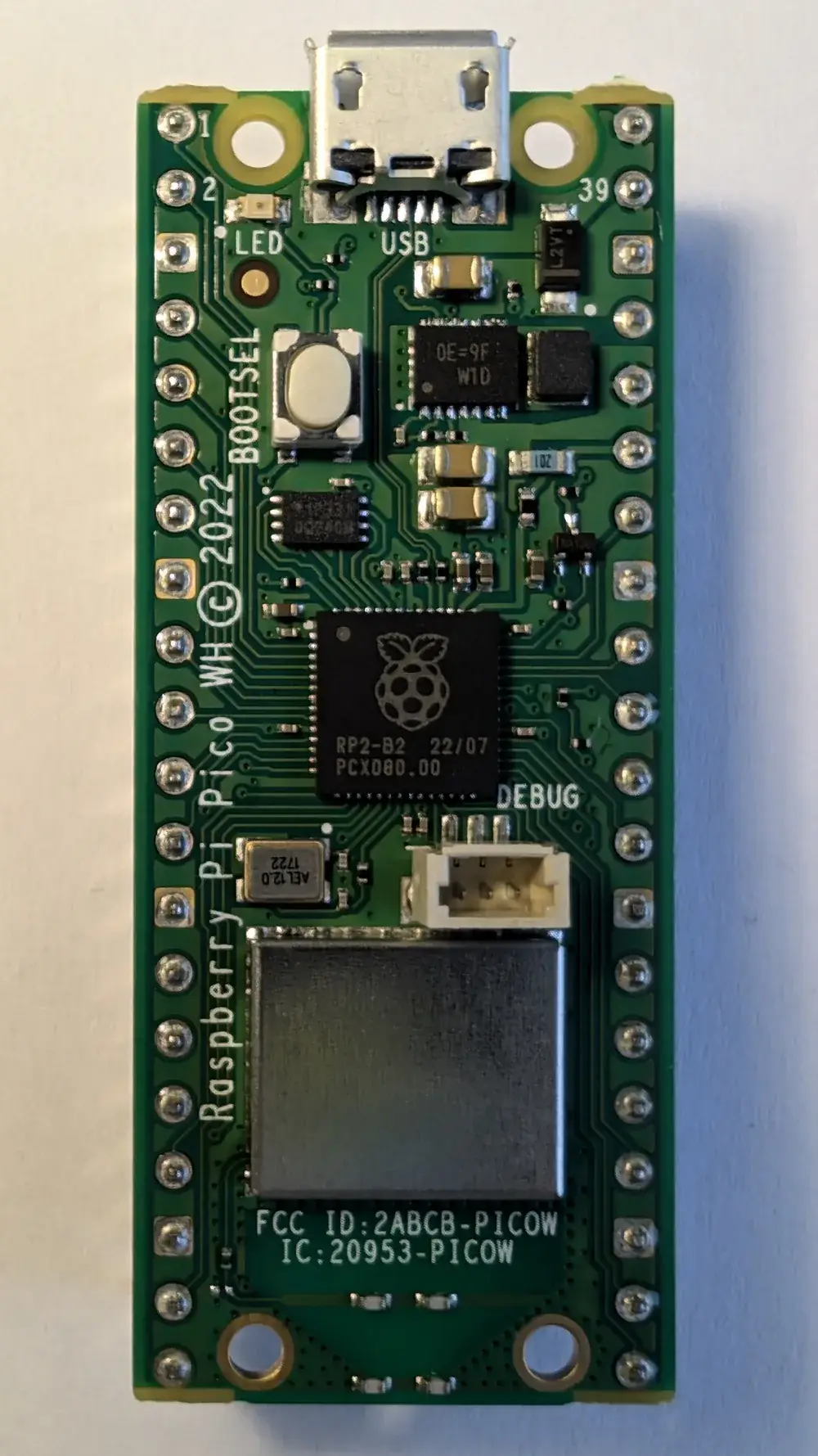
A Raspberry Pi Pico W board.
Pinout
Hover or tap a pin above to see what it does.
The Pico and Pico W share the exact same physical header — every pin on this diagram applies to both boards. The differences between them are all internal (covered below), not on the header itself.
GP-numbers, not GPIO-numbers
Every pin is labelled GPn on the silkscreen (GP0, GP1, and so on up to GP28), not GPIO0/GPIO1 the way a full Raspberry Pi’s header is. There’s no separate “physical pin number vs. logical number” split here the way there is on a Pi — the GP number printed next to the pin is the number MicroPython or the Arduino-Pico core expects in code. That’s genuinely simpler than the full-size Pi, and one less thing to get wrong.
The four numbers missing from the sequence
Look closely at the diagram and you’ll notice GP23, GP24, GP25, and GP29 are absent — the GPIO numbering jumps from GP22 straight to GP26. That’s not a typo. The RP2040 chip has 30 GPIOs internally, but only 26 of them are wired out to the header; the other four are permanently connected to specific jobs on the board itself:
- GP23 controls the onboard switching regulator’s power-save mode.
- GP24 senses whether USB VBUS is present.
- GP25 drives the onboard LED (on the original Pico — see below for the Pico W difference).
- GP29 is wired internally to measure VSYS ÷ 3, so the board can monitor its own supply voltage via the ADC.
None of these four are broken out to a header pin on either board, so there’s no physical pin lost by this — it just explains why the numbering has gaps, and why you’ll occasionally see example code reference GP25 for the LED and wonder where the corresponding header pin is. There isn’t one.
The one real Pico vs. Pico W difference
On the plain Pico, GP25 lights the onboard LED directly, and GP24/GP23/GP29 do the VBUS-sense, power-save, and voltage-monitoring jobs listed above. On the Pico W, all four of those same GPIO numbers are repurposed to run a small SPI-like link to the onboard Infineon CYW43439 wireless chip instead — GP23 enables it, GP24 carries data, GP25 is its chip-select, and GP29 is its clock. As a side effect, the Pico W’s onboard LED isn’t wired to GP25 at all anymore; it’s controlled through the wireless chip, which is why machine.Pin("LED") (rather than a raw pin number) is the portable way to blink it in MicroPython — that name resolves to the right mechanism on whichever board it’s running on.
Practically: since none of GP23/24/25/29 were ever available on the header to begin with, this difference is invisible to anything wired to the 40 header pins. It only bites if code borrowed from a plain-Pico project tries to read GP25 or GP29 directly on a Pico W expecting the old behaviour.
Power pins — don’t mix these two up
VBUS (pin 40) is raw, unregulated 5V straight from the USB connector, present only when a USB cable is plugged in and supplying power. VSYS (pin 39) is the board’s main power input more generally — feed it anywhere from 1.8V to 5.5V (a couple of AA batteries, a LiPo cell, a bench supply) and the Pico’s onboard regulator handles the rest. If you’re running the board from USB, VBUS is doing the work upstream and VSYS is being fed internally from it; if you’re running from battery, feed VSYS directly and leave VBUS alone. Never feed both from two different sources at once.
3V3(OUT) (pin 36) is the output of the onboard 3.3V regulator, meant for powering small external modules like sensors — it is not an input, and back-feeding a separate 3.3V supply into it fights the regulator.
ADC pins
GP26, GP27, and GP28 double as ADC0, ADC1, and ADC2 — three general-purpose analogue inputs, handy for potentiometers, thermistors, and analogue sensor outputs without needing an external ADC module. AGND (pin 33) is a separate, dedicated ground for these analogue readings; using it instead of an ordinary GND pin reduces noise from digital switching elsewhere on the board bleeding into an analogue measurement, which matters more than it sounds like it should when a sensor reading is jittering for no obvious reason.
This header layout carries forward unchanged to the newer Pico 2 and Pico 2 W too — Raspberry Pi kept the pin-for-pin layout deliberately so existing add-on boards and wiring still work, even though the chip underneath changed from the RP2040 to the newer dual Cortex-M33/RISC-V RP2350. A FREENOVE Pico 2 W is a reasonable way in if you’re buying new — everything on this page applies to it directly.
If you’re setting this board up for the first time, the Pico W Arduino IDE setup guide covers getting from a blank board to a working toolchain.
