The ESP32 DevKit’s biggest pinout trap isn’t a wiring mistake, it’s picking a GPIO that looks perfectly ordinary on the silkscreen but is secretly wired into either the onboard flash chip or the chip’s own boot sequence. Use one of those for an LED or a sensor and the symptom usually isn’t “doesn’t work” — it’s “won’t boot at all” or “uploads fail intermittently,” which sends people troubleshooting drivers and cables when the actual problem is a single pin choice.
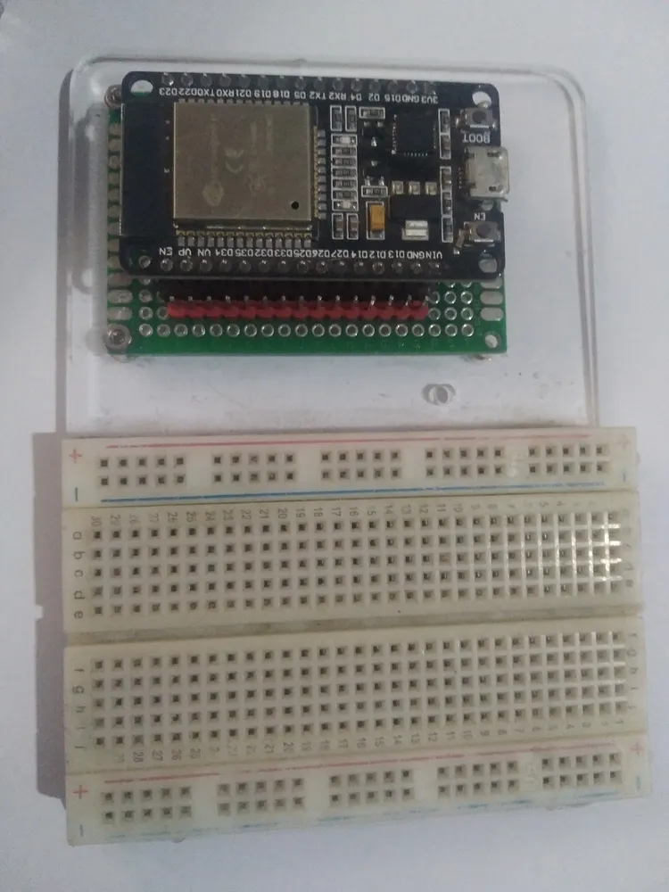
An ESP32 DevKit board. Photo: Edwiyanto, CC BY-SA 4.0 (resized)
Pinout
Hover or tap a pin above to see what it does.
This diagram matches the labelling on a common 30-pin ESP32 DevKit board (the layout above is transcribed directly from the board pictured at the top of this post). The pin functions below apply to any ESP32-WROOM-32 DevKit regardless of exact pin count or silkscreen wording — see the next section for why the physical layout itself isn’t fully standardised.
Which board is “the” ESP32 DevKit?
There isn’t one single official layout — “ESP32 DevKit” covers a whole family of near-identical breakout boards built around the ESP32-WROOM-32 module, sold with 30, 36, or 38 pins depending on the manufacturer, and different manufacturers don’t even agree on the order pins run down each edge. The pin functions — which GPIO does what, which ones are dangerous to touch — are consistent across all of them, which is what the rest of this reference focuses on.
Power and control pins
| Pin | What it does |
|---|---|
| 3V3 | Regulated 3.3V output — powers the module itself; also usable as a supply for small external components. |
| GND | Ground, usually broken out in two or three places around the board. |
| 5V / VIN | 5V input, fed from the USB port when connected, or usable to power the board externally. |
| EN | Enable/reset — pulling this LOW resets the chip. Most boards wire a physical reset button to this pin. |
GPIO0 and GPIO2: the boot-mode pins
These two decide what the chip does on power-up, and they’re the source of most “why won’t my ESP32 upload” confusion:
- GPIO0 sets boot mode. Floating or pulled HIGH (the normal state) boots your uploaded program; pulled LOW at the moment of reset drops the chip into flashing mode instead. Most DevKit boards wire a “BOOT” button to this pin for exactly that reason. If a project holds GPIO0 LOW for its own purposes (a button, a pull-down sensor), the board can fail to boot normally until that load is removed.
- GPIO2 is checked during boot and must be either floating or LOW — pulling it HIGH at reset can prevent booting on some board revisions. It’s also wired to the onboard LED on many DevKits, so lighting that LED is usually safe, but adding a second pull-up load on GPIO2 is worth avoiding.
GPIO6–11: reserved for the onboard flash — do not use
These six pins connect internally to the ESP32-WROOM-32’s built-in SPI flash memory, and on most 30-pin boards they aren’t even broken out to a header for exactly this reason. On 36/38-pin variants that do expose them (often labelled SD0–SD3, CLK, CMD), using them for anything else will corrupt communication with the flash chip and crash the board. Skip these entirely regardless of what your board labels them.
Other strapping pins worth knowing about
GPIO12 sets the flash chip’s operating voltage at boot (an internal setting called VDD_SDIO). If GPIO12 is pulled HIGH by something attached to it during power-up, the chip can switch to expecting 1.8V flash and fail to boot on the 3.3V flash most DevKits actually have. Avoid driving this pin HIGH at startup — using it for an output that defaults LOW, or as an input with a pull-down, is fine.
GPIO15 is checked at boot too; pulling it LOW silences the chip’s diagnostic boot log over serial, which is harmless but worth knowing if your serial monitor suddenly goes quiet after wiring something to this pin.
Input-only pins
GPIO34, GPIO35, GPIO36 (labelled VP), and GPIO39 (labelled VN) can only be used as inputs — they have no internal pull-up or pull-down resistors and can’t drive an output at all. They’re genuinely useful for reading sensors or analog voltages, just remember you can’t wire an LED or anything else that needs to be driven onto these four.
GPIO1 and GPIO3 (TX0/RX0)
These carry serial communication to your computer over USB — the same channel used for uploading code and for Serial.print() output. They’ll work as general GPIO once the board’s running, but using them for anything wired-up during development makes uploading and debugging awkward, since your circuit will be fighting the USB-serial connection for the same two wires.
Everything else
The remaining pins — commonly GPIO4, 5, 13, 14, 16 through 19, and 21 through 33 depending on the board variant — are genuinely general-purpose: digital I/O, PWM, I2C, SPI, and most of them double as ADC inputs. These are the ones to reach for first for LEDs, buttons, and sensor wiring. One caveat: all ESP32 GPIO pins are 3.3V logic and are not 5V-tolerant on their inputs — feeding a 5V sensor signal (like an HC-SR04’s ECHO pin) straight into any of them risks damage over time; that specific fix is covered in the HC-SR04 wiring guide.
A note on specialised ESP32 boards
Not every “ESP32 board” follows this layout at all. I run a Heltec-made LoRa/OLED combo board (sold under a few different Amazon listing names) with Meshtastic firmware, and its pinout is substantially different from a plain DevKit — a chunk of GPIOs are permanently committed to driving the onboard SX1262 LoRa radio over SPI and the built-in OLED over I2C, and are not available for general use even though they’re technically still GPIO pins on the same chip. If your board has an integrated display, radio module, or battery charging circuit built in, check that manufacturer’s specific pin map before assuming the generic layout above applies — the underlying ESP32 rules (don’t touch GPIO6–11, watch the strapping pins) still hold, but which physical pins are actually free to use will differ.
If your board keeps resetting mid-project rather than failing to boot outright, that’s usually a power issue rather than a pinout one — see why does my ESP32 keep disconnecting from Wi-Fi and ESP32 brownout detector triggered for the two most common causes.

