The 741 is the op-amp every electronics textbook still teaches from, even though it’s decades behind modern designs on almost every spec — it’s slow, it needs more supply voltage than most microcontroller-adjacent projects have lying around, and it’s been thoroughly superseded for new designs. It earns its place here anyway, because “how does an op-amp work” is usually taught against this exact chip, and understanding its quirks makes every other op-amp’s datasheet easier to read.
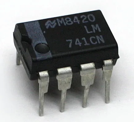
An LM741CN op-amp, DIP package. Photo: Olli Niemitalo, CC0 (resized)
Pinout
Hover or tap a pin above to see what it does.
Looking at the chip from above, notch or dot at pin 1, standard DIP-8 package:
| Pin | Name | What it does |
|---|---|---|
| 1 | Offset Null | Connects to a trim potentiometer (with pin 5) to cancel input offset voltage |
| 2 | −IN | Inverting input |
| 3 | +IN | Non-inverting input |
| 4 | V− | Negative supply |
| 5 | Offset Null | Other end of the trim potentiometer from pin 1 |
| 6 | OUT | Output |
| 7 | V+ | Positive supply |
| 8 | NC | No internal connection |
The thing that actually matters: it needs a genuine split supply
Unlike the LM358, which was specifically designed to run happily from a single positive rail, the 741 expects a true split supply — a positive voltage on V+, a negative voltage on V−, and ground sitting in between the two, typically ±5V to ±15V. Feed it 0V on pin 4 instead of a genuine negative voltage, the way a single-supply circuit would, and the input and output stages don’t have the headroom to work as designed — signals that should swing both above and below ground simply can’t, since there’s no negative rail for them to swing into.
This is the single biggest practical difference from the LM358 and the main reason the LM358 has mostly displaced the 741 in modern single-supply, battery- or microcontroller-powered designs — generating a clean negative rail just to run an amplifier is real added complexity that a lot of projects would rather avoid entirely.
Offset null — what it’s actually for
No real op-amp has perfectly matched input transistors, so even with both inputs tied to exactly the same voltage, a small unwanted offset voltage appears at the output. For most hobbyist projects this offset is small enough to ignore. Where it does matter — precision measurement, audio work where a tiny DC offset causes issues downstream — pins 1 and 5 let you wire a trim potentiometer (typically around 10kΩ, wiper to V−) to null that offset out manually. If a circuit doesn’t need this precision, leave both pins unconnected; they don’t need to be tied anywhere to work.
Output can’t swing to the rails, and it’s slow
Two limitations are worth knowing before assuming a circuit is misbehaving:
The output doesn’t reach all the way to V+ or V−. Like most op-amps of this generation, expect the 741’s output to fall short of each supply rail by a volt or two — a circuit designed assuming full rail-to-rail output will clip earlier than expected.
The slew rate is genuinely slow — around 0.5V/µs. That’s fine for audio-frequency signals and slow-changing sensor circuits, but it means the 741 can’t track a fast-changing signal accurately; ask it to amplify something switching in the microsecond range and the output will visibly fail to keep up, appearing as a rounded, sluggish version of what it should be rather than a clean amplified copy.
Common mistakes
Feeding it a single supply and expecting normal behaviour. Covered above — the 741 needs V− genuinely below ground, not just tied to it.
Leaving offset null pins connected to something other than a trim pot or nothing. Wiring pin 1 or 5 to a random voltage rather than either leaving them floating or using them correctly for trimming can push the output to an unexpected rail.
Assuming it’s fast enough for a given signal. The slow slew rate above is a real ceiling, not a minor caveat — if a circuit needs to track anything beyond audio-range frequencies cleanly, the 741 is the wrong choice regardless of how the rest of the circuit is built.
741 vs. LM358 — picking between them
If a project already has a single positive supply (a 5V microcontroller rail, a 9V battery with no negative rail generated), the LM358 is almost always the easier fit — no split supply needed, and it’s genuinely more common in modern hobbyist circuits for exactly that reason. Reach for the 741 specifically when a design already has (or needs to demonstrate) a proper split supply, or when following a textbook or classic circuit that’s built around it directly — the underlying op-amp theory is identical either way, which is really the 741’s lasting value at this point.
If you don’t have one on the bench, plenty of listings sell the 741 alongside other classic DIP-8 op-amps — check the datasheet pinout matches this one before assuming a drop-in swap with something else in the parts drawer. If you haven’t wired up a breadboard circuit before, how a breadboard is actually connected underneath is worth reading first.

