Every Raspberry Pi model since the B+ in 2014 — the 2, 3, 4, 5, and every Zero — shares the exact same 40-pin GPIO header, in the exact same physical order. That consistency is unusual in hobbyist electronics and genuinely useful: learn this header once and it applies to whichever Pi you actually own. The one thing that trips people up isn’t the wiring, it’s that every pin has two different numbers depending which one a tutorial happens to be using.
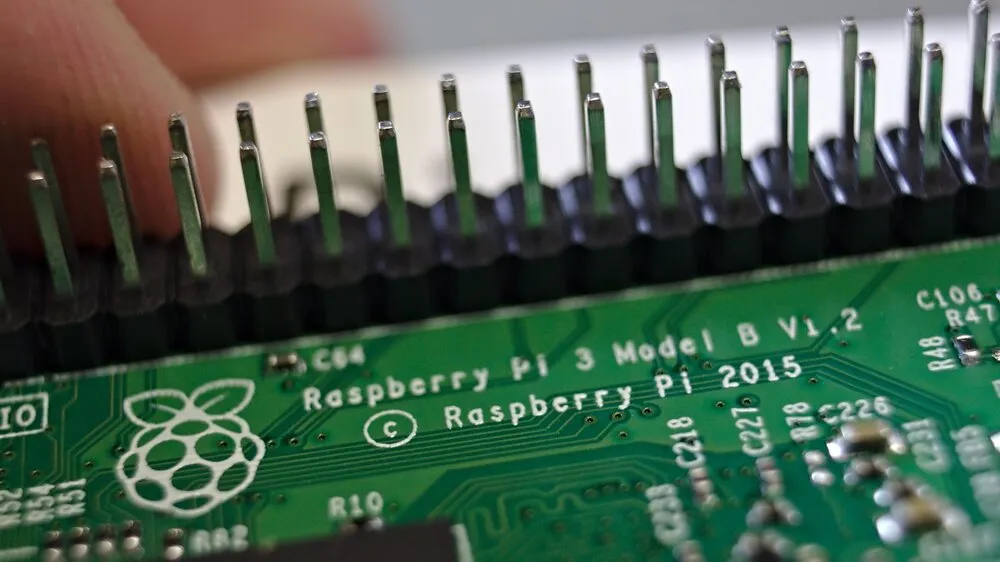
A Raspberry Pi’s 40-pin GPIO header. Photo: Florian Knodt, CC BY 2.0 (resized)
Pinout
Hover or tap a pin above to see what it does.
Physical pin numbers vs. GPIO numbers — the actual source of confusion
Every pin on the header has a physical position (1 through 40, counted left-to-right then top-to-bottom, starting from the corner nearest the SD card slot) and, for most of them, a separate BCM GPIO number (the number the Broadcom chip actually uses internally, and the number Python libraries like RPi.GPIO and gpiozero expect by default). These numbers don’t run in the same order — physical pin 12 is GPIO18, physical pin 29 is GPIO5, and so on — and mixing them up is the single most common reason a “correctly wired” GPIO project doesn’t respond. If code targeting GPIO17 doesn’t seem to do anything, and the wire is actually in physical pin 17, that’s the mismatch: physical pin 17 is a 3.3V power pin, not GPIO17 at all.
When in doubt, run pinout in a terminal on the Pi itself (part of the gpiozero package, usually preinstalled on Raspberry Pi OS) — it prints a live labelled diagram of your specific board’s header using both numbering schemes side by side.
The pins with fixed jobs
Pins 1, 2, 4, and 17 are power output — pins 1 and 17 give 3.3V, pins 2 and 4 give 5V. These aren’t GPIOs and can’t be reconfigured; use them to power external modules, not to read or write digital signals.
GPIO2 and GPIO3 (physical pins 3 and 5) are the I2C bus (SDA and SCL) and are the one pair of GPIOs with permanent physical pull-up resistors built into the board itself — every other GPIO needs its pull-up or pull-down configured in software or wired externally if one’s needed.
GPIO14 and GPIO15 (physical pins 8 and 10) are the UART, and on a default Raspberry Pi OS setup they may still be connected to the console serial port — worth checking raspi-config’s serial settings before wiring anything permanent to these two if the project needs the UART for something else.
GPIO0 and GPIO1 (physical pins 27 and 28) are reserved for HAT identification — they’re used to read an ID EEPROM on official HATs at boot, and using them for general I/O risks interfering with that process. Leave them alone unless a project specifically needs them.
GPIO7 through GPIO11 (physical pins 26, 24, 21, 19, 23) are the hardware SPI0 bus. They work fine as general I/O if SPI isn’t in use, but if a project already has an SPI display or ADC connected, these five are already spoken for.
Everything else is genuinely general-purpose — safe to use for LEDs, buttons, and most sensor wiring without any of the caveats above.
The two things that actually cause damage
All 40 pins are 3.3V logic, and none of them are 5V-tolerant. This is the one hard rule: feeding a 5V signal into any GPIO pin — a 5V sensor output, a 5V logic-level shifter wired backwards — can permanently damage that pin or the whole board. Always check a module’s logic voltage before connecting it directly; the exact same issue is covered from the sensor side in the HC-SR04 wiring guide, where the sensor’s 5V ECHO output needs a voltage divider before it’s safe to connect to a Pi.
Each GPIO pin can only source a small amount of current — nowhere near enough to drive a motor, a relay coil, or a bright LED strip directly. The commonly cited safe limit is around 16mA per pin, with roughly 50mA recommended as a ceiling across all GPIOs combined, to avoid stressing the board’s own power regulation. Anything that draws more than a basic LED needs a transistor, MOSFET, or driver module in between — never wire a motor straight to a GPIO pin expecting it to work.
If you’re chasing reboot or brownout symptoms rather than a GPIO wiring question, that’s more often a power supply problem than a pinout one — see why does my Raspberry Pi keep rebooting or crashing. And if you’re just trying to confirm the board itself is alive before worrying about GPIO at all, the green LED blink codes are the fastest first check.

