The Uno is the board most people learn Arduino on, and its pinout has stayed essentially unchanged since the R3 revision — which means this reference is good for pretty much any Uno you’ll actually encounter, genuine or clone. It’s also a simpler chip to reason about than an ESP32 or a Pi: every pin is 5V logic, there’s no separate GPIO-numbering scheme to trip over, and there’s really only a handful of things worth knowing beyond “digital pins do digital things, analog pins do analog things.”
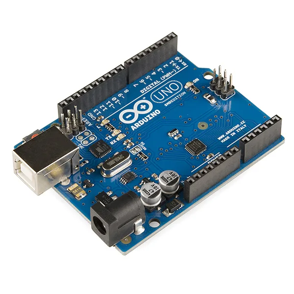
An Arduino Uno R3 board. Photo: SparkFun Electronics, CC BY 2.0 (resized)
Pinout
Hover or tap a pin above to see what it does.
Digital pins (0–13)
All fourteen are usable as general digital input or output. Six of them — 3, 5, 6, 9, 10, and 11 — are also capable of PWM (pulse-width modulation) output, marked with a ~ next to the pin number on the board’s silkscreen, and are the ones to reach for when a project needs to fade an LED or send a variable-speed signal to a motor driver rather than just switch something fully on or off.
Two are worth special attention:
- Pin 13 is wired straight to the onboard LED, which is why it’s the pin every “Blink” example sketch uses — no external LED or resistor needed to see it working.
- Pins 0 and 1 (RX and TX) carry serial communication to your computer over USB, the same channel used for uploading sketches and for
Serial.print()output. They work as regular digital pins once a sketch is running, but wiring anything permanent to them makes uploading and serial debugging awkward, since your circuit ends up sharing the same two wires as the USB connection.
Analog pins (A0–A5)
These read a voltage between 0V and 5V and convert it to a 0–1023 value via analogRead() — the standard way to read potentiometers, light-dependent resistors, and most analog sensors. They’re not exclusively analog either: all six can be used as ordinary digital I/O pins if a project runs out of digital ones, referenced in code as 14 through 19.
A4 and A5 double as the I2C bus (SDA and SCL) — the pins to use for I2C displays, sensors, and other I2C modules, the same SDA/SCL naming used on the ESP32 DevKit’s GPIO21/GPIO22 if a project moves between the two boards.
Power pins
| Pin | What it does |
|---|---|
| VIN | Unregulated input, typically 7–12V, for powering the board from something other than USB — a 9V battery through a barrel jack, for example. |
| 5V | The board’s main logic rail — usable as an output to power small 5V modules, or in some setups as a direct power input. |
| 3V3 | A separate 3.3V output, sourced from the onboard USB-serial chip’s own regulator. It’s low current — fine for a single 3.3V sensor, not enough to power a whole 3.3V board. |
| GND | Ground — there are several GND pins spread across the headers; any of them works. |
| RESET | Pulling this LOW resets the chip, same as pressing the onboard reset button. |
| IOREF | Reports the board’s logic voltage (5V on the Uno) so shields can auto-detect it. It’s not a power pin itself — don’t feed anything into it. |
That VIN-to-5V conversion is done by an onboard linear voltage regulator, working on exactly the same principle as the 7805 covered here — including the same “excess voltage becomes heat” tradeoff, which is part of why the Uno’s official recommended VIN range tops out around 12V rather than accepting anything higher.
The one electrical rule that matters most
Every pin on the Uno is 5V logic, unlike the 3.3V-only pins on an ESP32 or Raspberry Pi. That cuts both ways: a 5V sensor connects to the Uno directly with no level-shifting needed, but wiring a 3.3V-only module (many newer sensor breakouts, some radio modules) straight to an Uno’s output risks over-driving it. Check a module’s logic voltage before assuming it’s a straight swap between an Uno project and an ESP32 or Pi one.
If a sketch uploads fine but the board seems to reset or misbehave once it’s actually running, that’s usually a power or brownout issue rather than a pin mistake — see why does my Arduino keep resetting.

